Our Location
Brugata 1
0186 Oslo
Norway
There is now a new video out documenting how Recore A5 is tested and calibrated. This blog post will act as a supplement to the video, giving some more detail and offering the material as a readable reference.
The testing procedure for Recore is done by the board itself. This is convenient because it makes it easy to access the data available on the board, such as values that must be collected from various sensors. These are:
All the analog values are gathered by the microcontroller on the board and sent to the SoC via UART. In addition to this, all inputs and outputs must be tested. These are:
The stepper motors and endstops are tested together, simply letting the motor run until the endstops are hit. The HDMI is tested by sending a known image to a Manga Screen with a USB webcam pointed at it and using ImageMagick to check for similarity. Ethernet speed is tested using Iperf. Mosfet outputs are tested by checking that the on and off values are correct using a separate microcontroller on the testing jig.
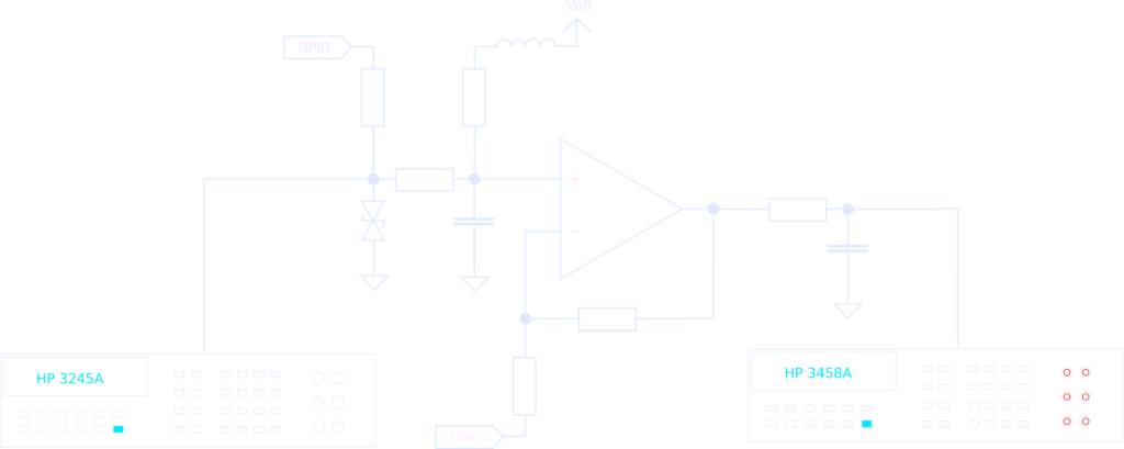
It’s great to have good equipment for running the tests, but where the equipment is really needed is during calibration of the gain and offset for the programmable instrumentation amplifier. The thermistor/thermocouple inputs can be programmed to have either a 1 time gain or a 101 times gain. This is done by either pulling a resistor low using a GPIO pin or by setting it to high Z which will eliminate it from the equation. There is also a programmable pull-up that can be used to create a voltage divider for a thermistor.
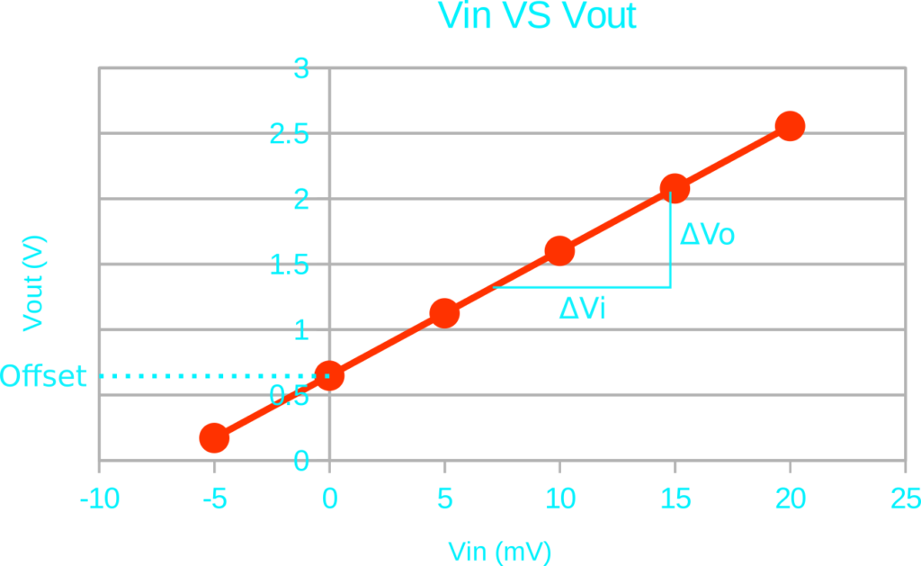
With this setup, the amplification at various voltage levels can be measured. From this, using linear regression, the gain and offset can be calculated as G = ΔVo/ΔVi. The offset is simply the output value measured at 0 volt input. The offset value can be measured by the end user by shorting the input to ground, disabling the pull-up and setting the gain to 101.
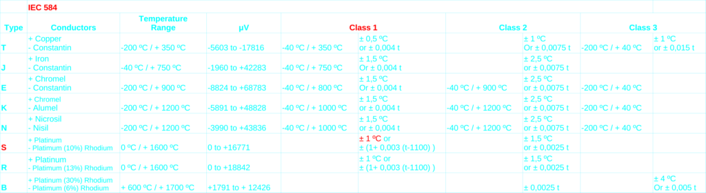
In the video, I mention that the tolerance of the resistors used are ±1 %, but a good thermocouple can have a 1 degree accuracy across the temperature range. These are values that do not easily compare, so allow me to clarify. A type S thermocouple is actually not that much in use any more, but regardless, the tolerance is very good. ± 1 ºC from 0 to 1100, which is < ± 0.1 %. Below is the IEC 584 chart used as reference.
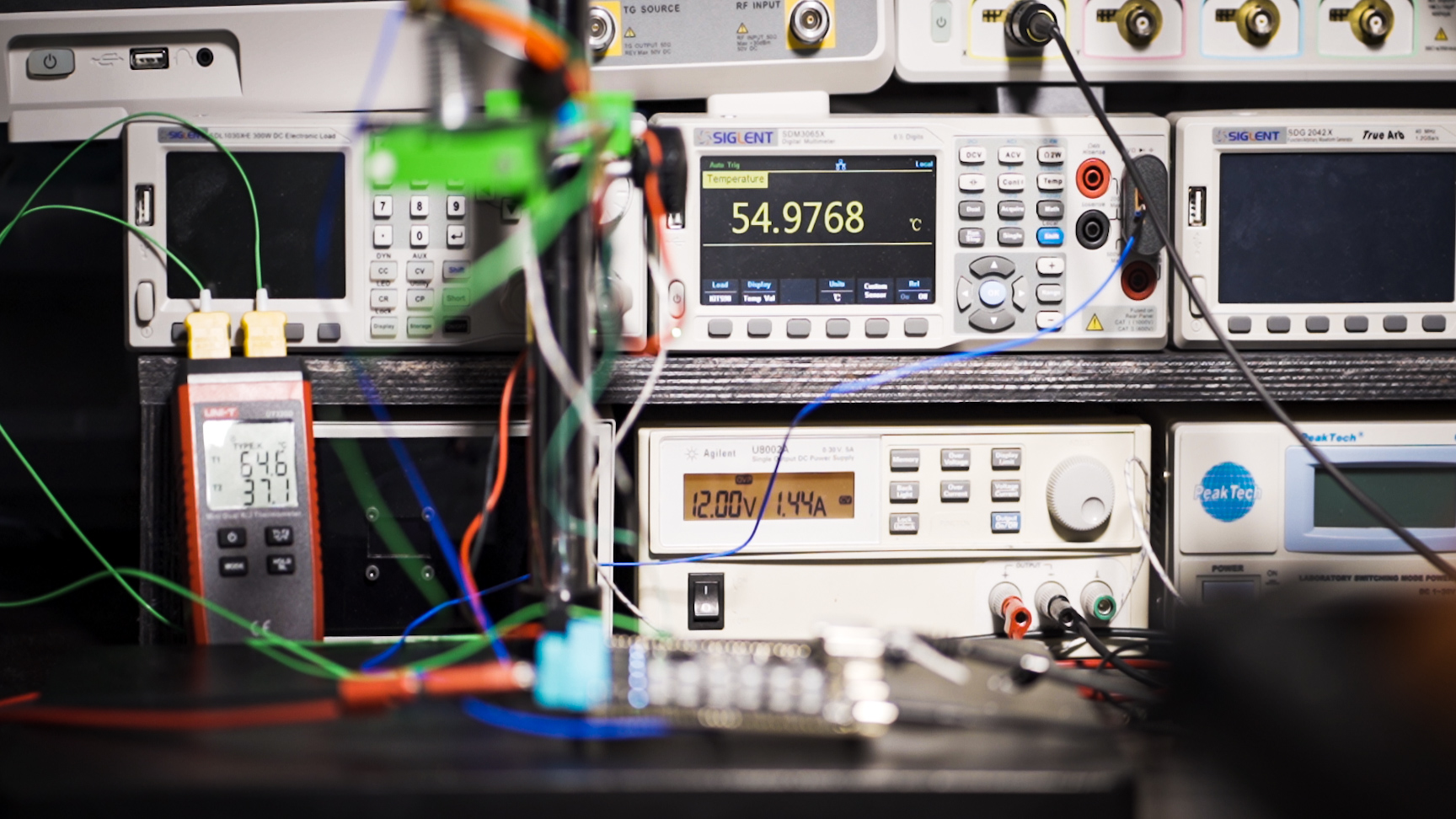
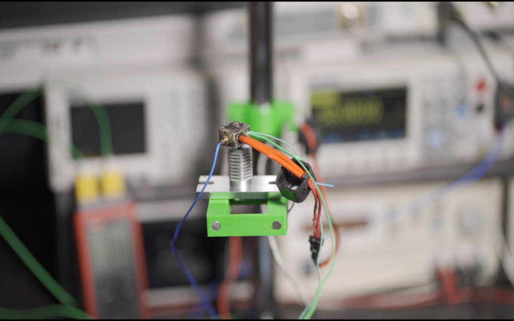
The video ends with an experiment comparing three thermocouples. Unfortunately, I don’t yet have a proper thermometer that I trust, so the results must be taken with a grain of salt. Also, the test was conducted with a fast temperature rise followed by a gradual cool down. This is not ideal since the temperature in the aluminum block needs time to reach equilibrium. A better test would be to use a dry-well and allow the well to settle at different levels. Still, during the cool-down, the temperatures actually matched pretty well for a large range of values.
Comments are closed.
[…] 3D printing board developer [Elias Bakken] have Release of automatic test procedures He used a stack of four (at least) old HP test equipment for development. In addition, his test […]